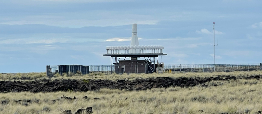
Very High Frequency (VHF) Omnidirectional Range (VOR)
Very High Frequency Omnidirectional Range (VOR) is a radio navigational system that allows pilots to determine their bearing relative to a ground station by receiving a VHF radio signal.
VOR stations emit two signals: a reference signal and a variable signal. By comparing these signals,
the aircraft’s receiver can calculate the aircraft’s beating to or from the VOR station, providing an
accurate position fix.
VOR stations are used for en-route navigation and instrument approaches.
Pilots follow radial lines emanating from the station to navigate accurately.
VOR navigation has been a key part of aviation navigation for decades. However with the trend in aviation towards more advanced navigation technologies, the FAA are in the process of phasing out of VOR systems.
The FAA has been gradually reducing the number of VOR stations while transitioning to a more GPS-focused system. While there is no definitive end date for VOR operations, significant reductions in VOR coverage are expected over the next few years, particularly as newer aircraft are equipped with advanced navigation systems.
Advancements in technology such as the introduction of satellite-based navigation systems, such as GPS (Global Positioning System), provides more accurate, reliable, and flexible navigation options.
Cost of Maintenance – maintaining VOR infrastructure is expensive, and as fewer and fewer aircraft rely on it, the cost-effectiveness of keeping these systems operational diminishes.
Modern navigation technologies allow for more direct flight paths and reduced air traffic congestion, which enhances efficiency in the aviation system.
While VOR has played a critical role in aviation navigation for decades, the shift towards modern technologies is reshaping how pilots navigate the skies.
Currently in 2025 VOR is still a technology that forms part of the overall toolkit of the suite of navigation tools that every pilot should be proficient in the use of.
Key Features of VOR
- Frequency: VOR stations operate in the VHF range, specifically from 108.0 to 117.95 MHz.
- Omnidirectional: The VOR signal is broadcast in all directions, making it accessible from multiple paths.
- Radial Information: Pilots use VOR to navigate along specific radials, which are the imaginary lines extending outward from the VOR station.
- DME Integration: Many VOR stations are paired with Distance Measuring Equipment (DME), which provides distance information to the pilot.
- Use in Aviation: VOR is commonly used for en-route navigation, approach procedures, and in instrument flight rules (IFR) conditions.
- Accuracy: VOR provides reliable navigation information.
- Range: VOR signals can be received from a distance of 25 to 200 nautical miles, depending on altitude and terrain.
Limitations of VOR:
- Line of Sight: VOR signals can be obstructed by terrain and buildings.
- Signal Interference: Atmospheric conditions and other electronic signals can affect accuracy.
Types of VOR
For civilian flight operations (non-military) there are 3 types of VORs:
- VOR
- VOR/DME – A VOR co-located with DME (Distance Measuring Equipment)
- VORTAC – TAC stands for TACAN and is for military use only.
- To civilian pilots, VORTAC and VOR/DME mean the same thing.
Instruments
Pilots use a combination of instruments and systems in the cockpit to track VOR (Very High Frequency Omnidirectional Range) stations.
VOR Receiver
To receive VOR radio signals, the aircraft must be equipped with a VOR receiver that tunes into the specific VOR frequency, which is typically in the VHF range between 108.0 and 117.95 MHz.
The receiver processes the signals from ground-based VOR stations.
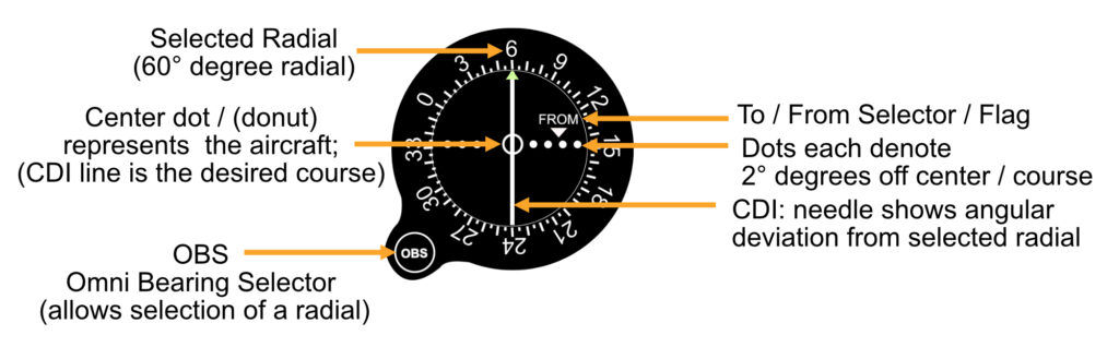
A VOR receiver has three elements:
- Omnibearing selector (OBS),
- Course deviation indicator (CDI)
- TO / FROM indicator
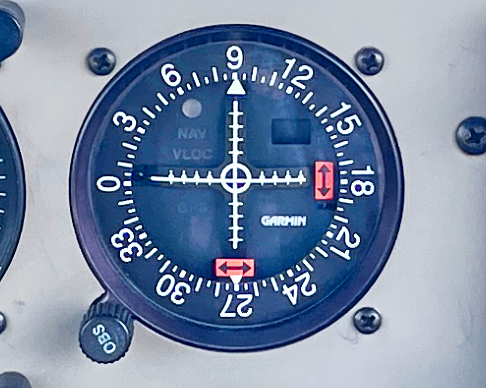
CDI (Course Deviation Indicator):
The CDI (or needle) shows how far the aircraft is from the selected radial or course. A needle moves left or right to indicate whether the plane is on course, and the pilot adjusts the heading to bring the needle back to the center (indicating the aircraft is tracking the VOR correctly).
When the aircraft is not on the chosen radial, there are white marks (or dots) that indicate each 2° off the radial the aircraft is.
OBS (Omnibearing Selector)
The OBS knob is used to select a specific radial or course from the VOR station. The Pilot rotates the OBS to choose the radial they want to track, which adjusts the CDI to show deviations from that radial.
DME (Distance Measuring Equipment)
Many VOR stations also have co-located DME equipment, which gives the pilot distance information to the station. The DME provides distance in nautical miles (NM), helping the pilot determine their exact range from the VOR.
For civilian flight operations (non-military) there are 3 types of VORs:
- Very High Frequency means that VORs operate on a frequency range between 108.0 and 117.9 MHZ.
- Omni-direction Range means that VORs provide pilots with 360 degrees of Navigational Coverage.
- Operates works based on timing between 2 radio signals.
- One of the radio signals a VOR sends out is a Uni-Directional (sweeping) signal.
- The other signal is Omnidirectional (all-directions).
- Every time the sweeping, uni-directional signal points due North, the omnidirectional signal flashes.
- The radio signal project radials in all directions (360°) from the station, like spokes from the hub of a wheel.
- Each of these radials is denoted by its outbound magnetic direction.
- Almost all VOR stations will also be VORTACs. A VORTAC (VOR-Tactical Air Navigation), provides the standard bearing information of a VOR plus distance information to pilots of airplanes which have distance measuring equipment (DME).”
- Transmitting frequencies of VOR stations are in the VHF (very high frequency) band between 108 and 117.95 MHz, which are immediately below aviation communication frequencies.”
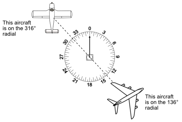
Radial
Understanding radials is fundamental for navigation, especially when using VOR, or VHF Omnidirectional Range, stations. Picture a VOR station as a point on a map that broadcasts signals in all directions, creating a network of invisible lines radiating outward like the spokes of a wheel. Each of these lines, known as radials, represents a unique direction from the station, measured in degrees from 0 to 359. These degrees correspond to compass directions: for example, the 090 radial points due east from the station, while the 180 radial points directly south.
For pilots, radials serve as reliable guides in the sky, helping them to determine their position and navigate along predetermined routes. An aircraft situated on a particular radial knows exactly where it is relative to the VOR station, which is crucial for flying assigned airways—highways in the sky defined by these radials. By tuning their VOR receiver to a specific station and selecting a radial, pilots can fly along a straight path either toward or away from the station. For instance, if a pilot sets their course to intercept the 270° radial and flies toward the VOR station, they are coming in from the west. If they follow the same radial outbound, they will be moving westward, away from the station.
Radials are especially important in complex airspace environments and around airports, where they are used to define waypoints, assist in approach and departure procedures, and establish holding patterns. In essence, radials create an organized and structured network that guides aircraft safely and precisely, even when visibility is poor or landmarks are few.
- A radial is defined as a line of magnetic bearing extending from an omnidirectional range (VOR).
- A VOR projects 360 radials from the station.
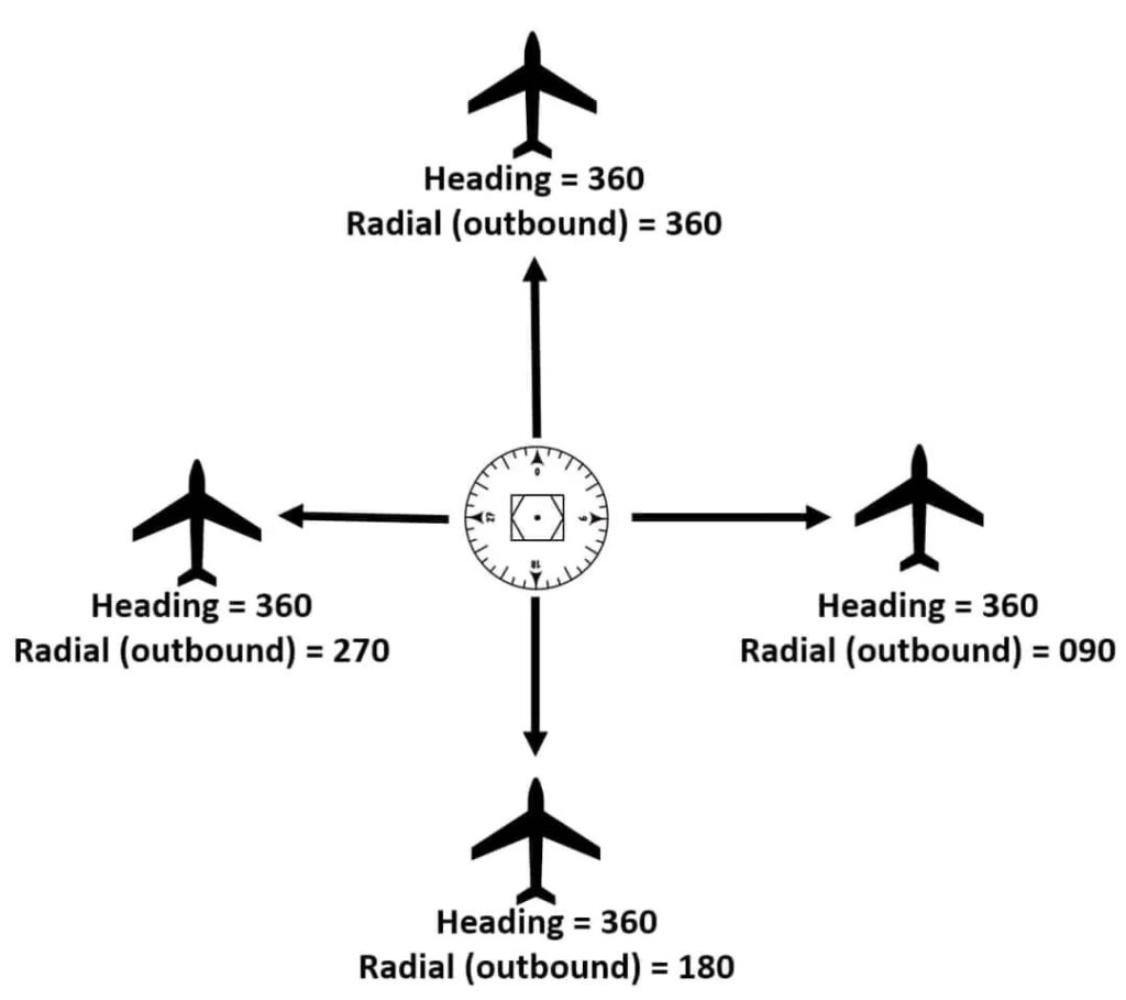
- These radials are always identified by their direction “from” the station.
- Regardless of heading, an aircraft on the 360° radial will always be located north of the station.
- A VOR works based on timing between 2 different radio signals.
- An omnidirectional signal. (all directions at once)
- A unidirectional, sweeping signal (signal is focused in one direction at a time)
- Each time the sweeping signal passes north, the omnidirectional signal flashes.
The airborne equipment receives both signals, looks (electronically) at the difference between the two signals, and interprets the result as a radial from the station.
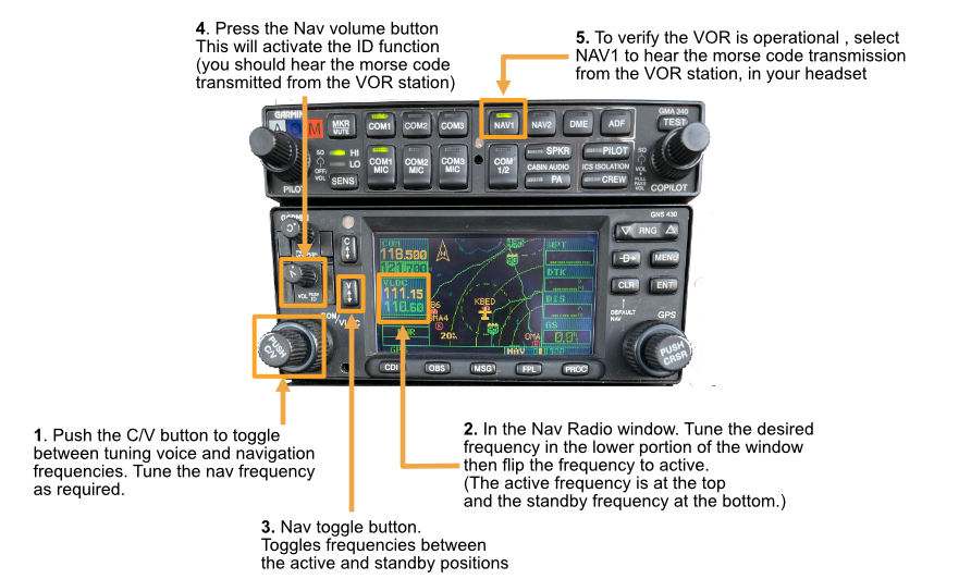
Tuning the nav radio to the VOR Frequency
To be able to utilize the VOR pilots must correctly set up the instruments to receive the VOR signal beginning with tuning your radio to the desired frequency of a nearby VOR station.
Once the radio equipment has been tuned to the VOR station you must ensure that you identify the station by listening to the 3-letter Morse code identifier that us transmitted on the frequency.
The VOR receiver is tuned into the desired VOR using the “Nav side” of the standard radio equipment found in training aircraft
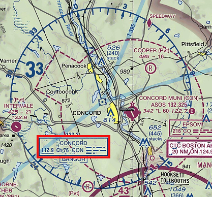
Finding a VOR’s frequency
To find the frequency of a VOR (VHF Omnidirectional Range) station, you can use several methods:
Navigation Charts: Look at sectional charts or terminal area charts. VOR frequencies are typically listed next to the VOR symbol (below)
- Flight Planning Software: Use flight planning applications or websites that provide VOR information, including frequencies.
FAA Resources: The FAA publishes the “Chart Supplement,” which includes details about all VOR stations in the U.S., including their frequencies.
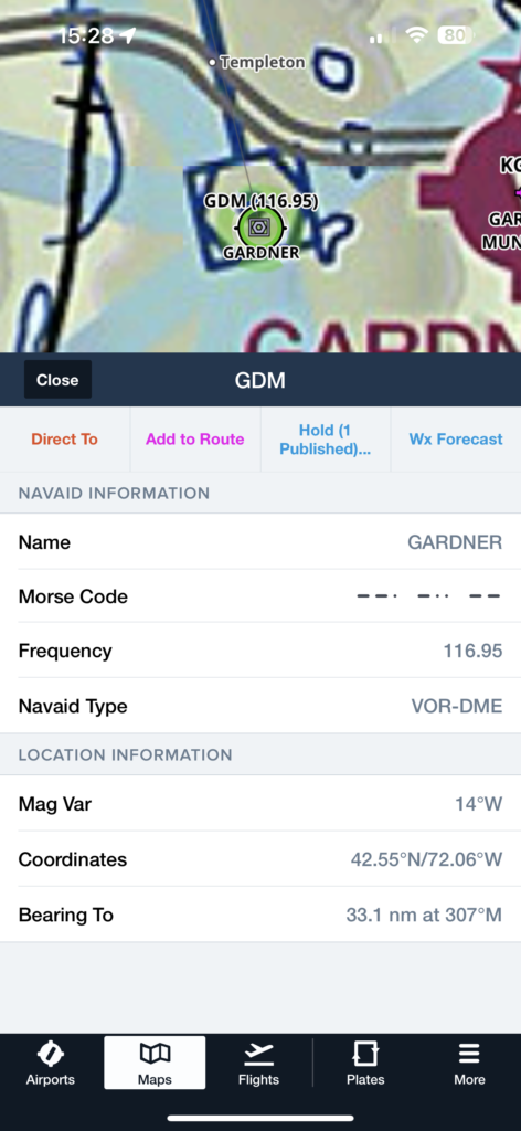
In-Flight Navigation Systems: If you’re in an aircraft with a GPS unit, you can search and enter the ID of the VOR station to find the VOR frequency directly from your navigation system, which often includes a database of frequencies.
Flying directly to a VOR
In order to fly directly to a VOR, tune into that VOR frequency and identify the station morse code.
- Using the OBS center the needle with a TO indication.
- Turn to that heading and bracket to stay on the line
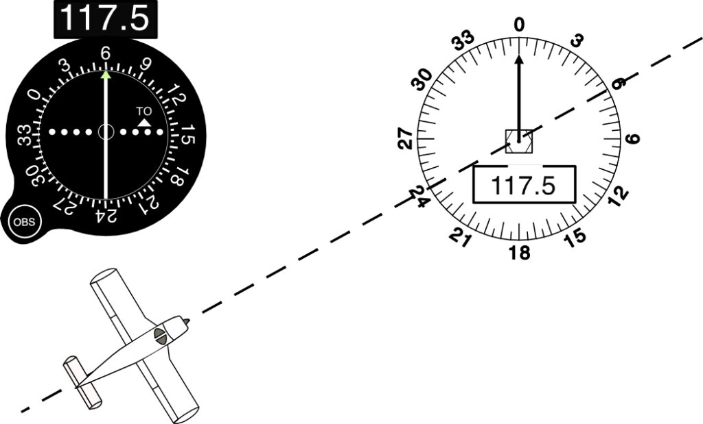
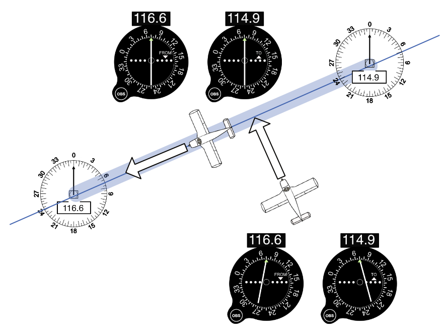
This example shows an airplane on the 240° radial but heading to the VOR on a heading of 60°
Having entered 60° on the VOR receiver the CDI will remain centered while you fly towards the VOR on the 240° radial with a heading of 60°
Flying from one VOR station to another
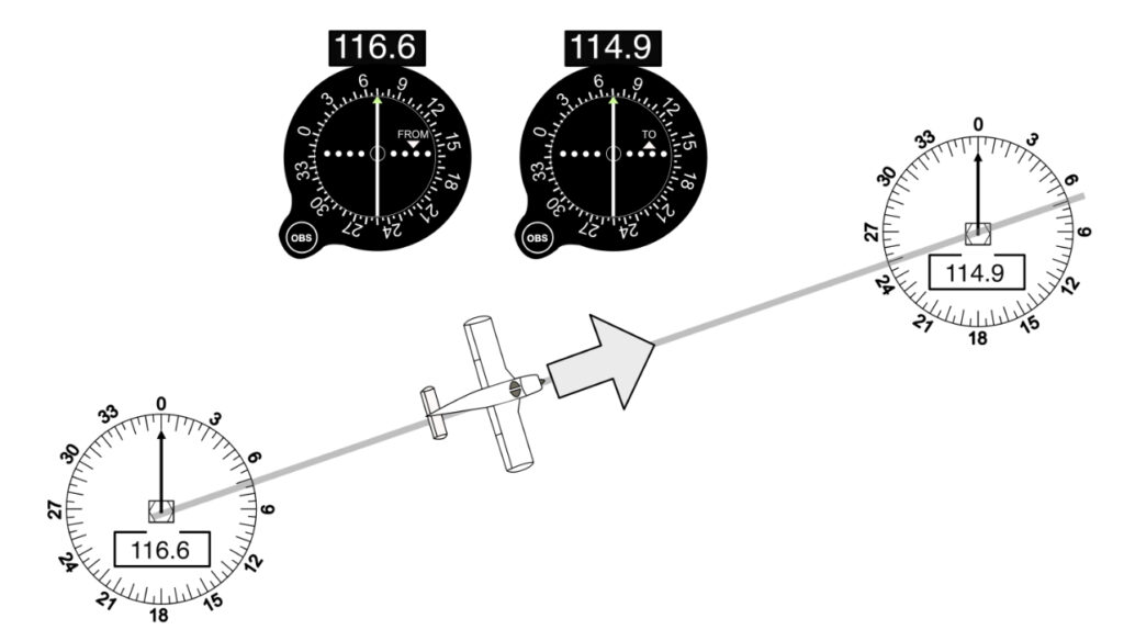
To fly from one VOR to another, fly away from one VOR with the needle centered on the appropriate radial and a FROM indication.
You can put exactly the same radial into the VOR you’re approaching, and it will also line up with a TO indication.
If you have only one VOR, switch between the frequencies at the half way point.
Intercepting a Radial
INTERCEPTING A RADIAL is a matter of choosing the angle at which you wish to get on the line, and then doing some simple math.
The most rapid way to get on to a distant radial would be to fly perpendicular, straight at a 90° intercept. To intercept a 270° TO course from the south, fly direct north until the needle centers. To intercept that same line (which would also be the 90° FROM radial) from the north, fly directly south.
Usually, though, you’ll want to intercept a course at a shallower angle, because that cuts down the total distance and time to your destination. 30° or 45° are good intercept angles, but any angle will do and the math is always the same: Take the magnetic course of the line that you want to be on.
Example:
If you’re trying to intercept the 280° course from the north on a 45° intercept, fly a track of (280°- 45°) = 235°
- If you were going to fly FROM on that same line, it’s the 100° radial.
- To intercept at a 45° angle from the north, you ‘re now on the left side of the line,
- so fly (100° + 45°) = 145°
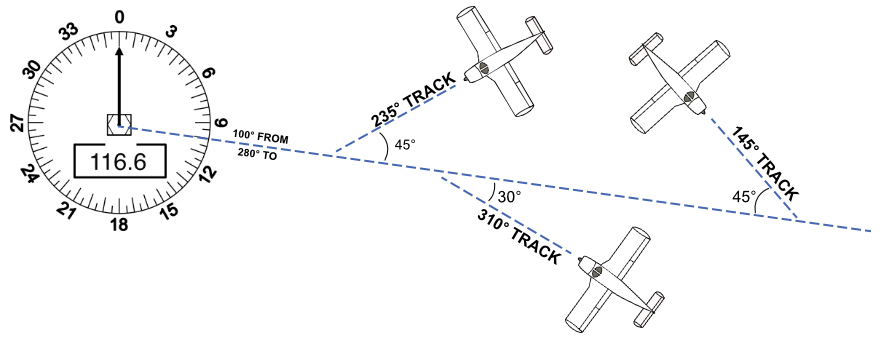
You’re trying to intercept the 280° course (TO the station) from south of that line.
You choose a 30° intercept. Fly a track of (280°+30°) = 310°
Note that the track is not necessarily the heading: you’ll have to crab for wind in order to intercept correctly.
Intercepting a victor highway
Victor airways are low-altitude airways. They are defined in straight-line segments, each of which is based on a straight line between either two VHF omnidirectional range (VOR) stations, or a VOR and a VOR intersection.
Fly a course that will intercept the airway.
Tune to the two VOR receivers on the airway, enter on the radials that defines the airway.
As you approach the airway the CDI needles will center.
When both needles are centered you are able to turn to either VOR and track towards the VOR.
You may also use the airway as a checkpoint on route to another destination
Course Deviation
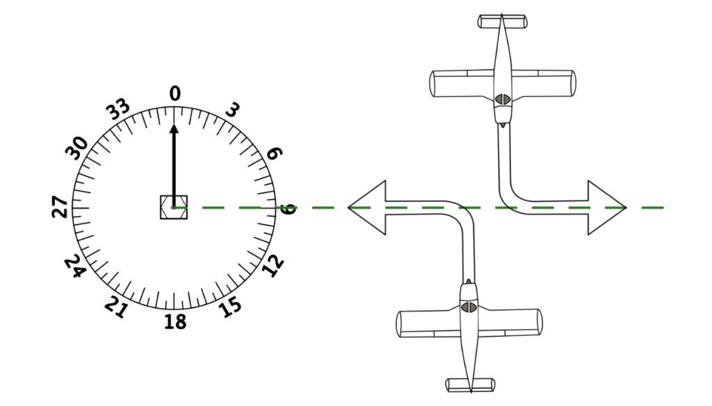
If the aircraft is not on the radial line, (shown as the dashed, line below)the CDI (needle) shows a deviation of one dot for every two degrees.
- Think of the center ring / dot as being the aircraft, and the CDI as being the line you want to be on.
- If the line is to the right of the dot, your desired radial is to your right – get back on it by turning right (red aircraft).
- If the line is to the left, go to the left (yellow aircraft).
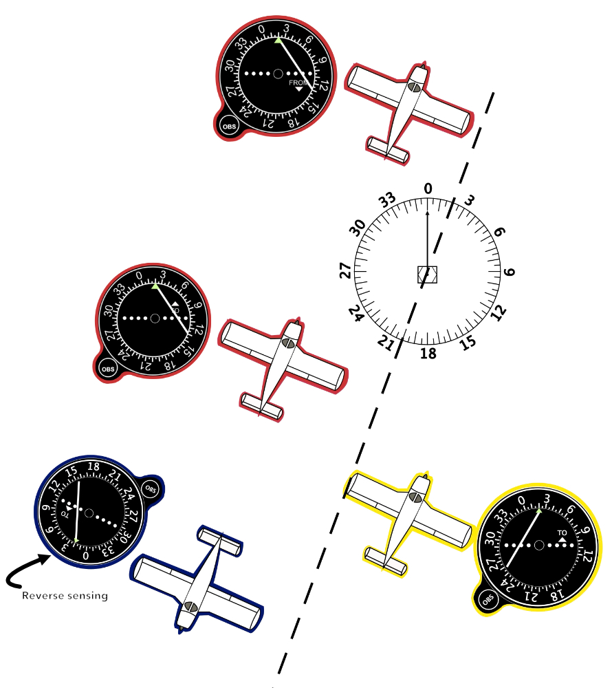
Reverse Sensing
IMPORTANT: if you are flying away from the VOR station, and the indicator says TO, you will get reverse sensing: the line will be on the wrong side.
This is the situation with the blue aircraft. If the blue plane goes right, toward the CDI needle, it will get farther away.
The same is true if you are flying toward the station, and the indicator says FROM.
Bracketing
Bracketing is a technique used in aviation to intercept and maintain a course towards or away from a VOR station. Pilots use this technique to correct for crosswind drift and keep the aircraft on the desired radial.
Steps in Bracketing:
Tune and Identify the VOR: The pilot tunes into the frequency of the VOR station on their navigation radio and confirms its Morse code identifier to ensure accuracy.
Set the Desired Radial: Using the aircraft’s navigation instruments, the pilot sets the OBS (Omni Bearing Selector) to the desired radial, either TO or FROM the station, depending on the direction of travel.
Determine Initial Intercept Heading:
When off course, a pilot needs to determine a heading that will intercept the desired radial. This is often done by turning towards the radial with an intercept angle of 20–30 degrees.
Once on course, the pilot should center the needle of the CDI (Course Deviation Indicator).
Observe Drift:
If the CDI needle starts moving off course due to wind, it’s a sign that the aircraft is being pushed off the radial.
The pilot notes the degree and direction of the drift.
Bracket the Correction:
If the wind is pushing the aircraft to the left of the radial, the pilot turns slightly to the right to correct.
After seeing where this new heading brings the CDI needle, they “bracket” by making smaller turns back and forth until the aircraft stays centered on the radial.
A pilot continues making slight heading adjustments (left and right) until finding the precise wind correction angle (WCA) that keeps the aircraft on course.
Maintain the Course:
Once the correct wind correction angle is found, the pilot maintains this heading to stay on the radial.
The bracketing process essentially involves narrowing down the heading needed to balance the wind drift.
Bracketing Example
- On a 0° / 360° course TO the station, you start with a heading of north (0° / 360°).
(If you already know which direction the wind is from, guess a crab angle.)
- Over time, because of wind, the aircraft goes off course, the CDI shows the deviation, the dots show each 2° off course.
- Choose a heading that will put the plane back on the line, say for example a 20° intercept: heading 340°
- When the CDI has again centered, split the difference between your intercept heading, and original heading: in this case, fly a new heading of 350°
- Again over time, the plane deviates, either by being blown with the wind, or drifting because of too much crab angle
- Choose another gentle intercept heading . .
- and then split the difference again: in this case, 350° is too much, but 360° too little. Fly heading 355° Repeat this bracketing process until you find a heading that holds the CDI steady.
DETERMINING YOUR POSITION USING VOR
- Determine the VOR frequencies, Tune to the VOR station and Identify the VOR morse code for the station
- Remember that radials are from the VOR, or leaving the VOR. (radiating outwards)
- To locate a position based on VOR radials, draw the radials on your chart.
- Make sure you have located the correct radial on the compass rose before drawing your line.
- Recheck yourself by counting in 10° or 5° intervals from each of the closest 30° intervals that are numbered and marked with an arrow.
- You must compare the OBS setting and the TO/FROM indicator with the aircraft heading.
- To indicate correctly, the OBS (top) setting must correspond roughly with the aircraft heading [e.g., 180° OBS (top) setting, 180° aircraft heading].
- The TO/FROM indicator must correspond to the aircraft’s flight path in relation to the VOR.
- Flying TO a VOR with a FROM indication and flying FROM a VOR with a TO indication will result in reverse sensing.
- When flying directly from a station, the heading and the radial being flown will correspond (i.e., 360° heading FROM will be the 360° radial).
- When flying directly TO a station, the heading flown and the radial being flown will be reciprocals (i.e., 180° heading TO will be on the 360° radial).
- With regard to CDI deflection, you must pretend your airplane has the same heading as the OBS setting. A left deflection means you are right of course and a correction to the left is needed, while a right deflection means you are left of course and a correction to the right is needed.
- If your heading and the OBS setting are not roughly the same, the CDI will not indicate correctly .
- If no TO or FROM flag indication appears, the aircraft is in the area of ambiguity, i.e., 90° away from the radial dialed up on the OBS.
- To know the side of the station on which the aircraft is located, consult the CDI. The needle points toward the station.
- Interpreting VOR indications.
- When you select a course in the OBS, imagine that you have drawn a line through the VOR station in the direction of the course.
- The line should extend outward from the VOR in both the direction of the selected course and the direction of its reciprocal.
- Imagine an arrowhead at the end of the line in the direction of the desired course, as in the diagram.
- You must compare the OBS setting and the TO/FROM indicator with the aircraft heading.