
§ 91.103 Preflight action.
Each pilot in command shall, before beginning a flight, become familiar with all available information concerning that flight.
The Navigation Log is a flight planning document used by pilots to plan and track cross country flights. It helps ensure safe and efficient navigation by providing a structured way to record and calculate various aspects of the flight.
Although the process of creating a Navigation Log has largely been superseded by technology, the knowledge and the process of completing this document prior to any cross country flight is still a crucial skill. Electronic Flight Bags (EFBs) with a flexible, digital interface to access navigation charts, weather information, and flight planning tool can automatically calculate estimated times, distances, fuel consumption, and performance data which can be accessed in the cockpit.
Despite these advancements, some pilots and operators still use traditional navigation logs for certain purposes, such as for cross-checking, backup, or in situations where technology might not be available or reliable.
Understanding the principles behind traditional navigation is essential for pilots to ensure they can handle situations where technology might fail or be unavailable.
Creating a Navigation Log remains an essential part of aviation preparation, helping pilots ensure safe and efficient navigation.
Download editable VFR Navigation Log form
VFR Cross Country Flight Planning Exercise
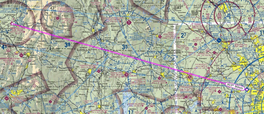
The scenario for this process is to create a VFR flight plan for a day VFR flight from Hanscom Airport KBED to Morse State Airport (Bennington) KDDH.
The flight will be conducted using pilotage – using visual landmarks (looking out of the window) for navigation. For this flight we will use paper VFR sectional charts, which emphasize objects that are easy to identify from the air, e.g., highways, towns, big towers, lakes etc.
Required Flight Planning Tools
To complete this planning exercise and fill in the VFR Nav Log you will need to the following items:
- New York sectional chart
- alternatively, use www.skyvector.com / foreflight etc
- Plotter
- E6B calculator (mechanical or electronic)
- Four function calculator
- Pencil
- Flight planning sheet (Navigation Log)
- Pilot’s Operating Handbook (POH)
Ground procedure:
- Plot planned course
- Check Sectional Chart for terrain and airspace (planning to transition or avoid airspaces, obstacles, restricted areas, open water etc)
- Select checkpoints along the route
- Measure distance from checkpoint to checkpoint
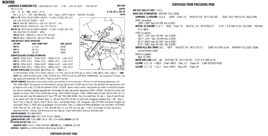
- Research airport info in Chart Supplement publication
- Check weather, including obtaining winds aloft
- Estimate likely time and fuel burn
- Verify weight and balance
- Verify sufficient performance for takeoff and landing on suitable-in-light-of-weather runways
- Develop flight plan and Nav Log
In-flight procedure
- Fly planned headings and airspeed. Make changes as required for wind.
- Note top of climb (TOC)
- At each checkpoint, use left / right deviation for wind correction
- Note times and distances against planned times and distances.
- Note top of descent (TOD)
- Make use of available ATC services (flight following)
Developing the Flight Plan
When developing the flight plan and filling out the Nav Log there are six questions you will need to answer.
- How am I getting from departure to destination?
- What are my checkpoints?
- What direction will I need to point the airplane?
- How high and fast will I be going?
- How long will it take to get there?
- How much fuel will I need?
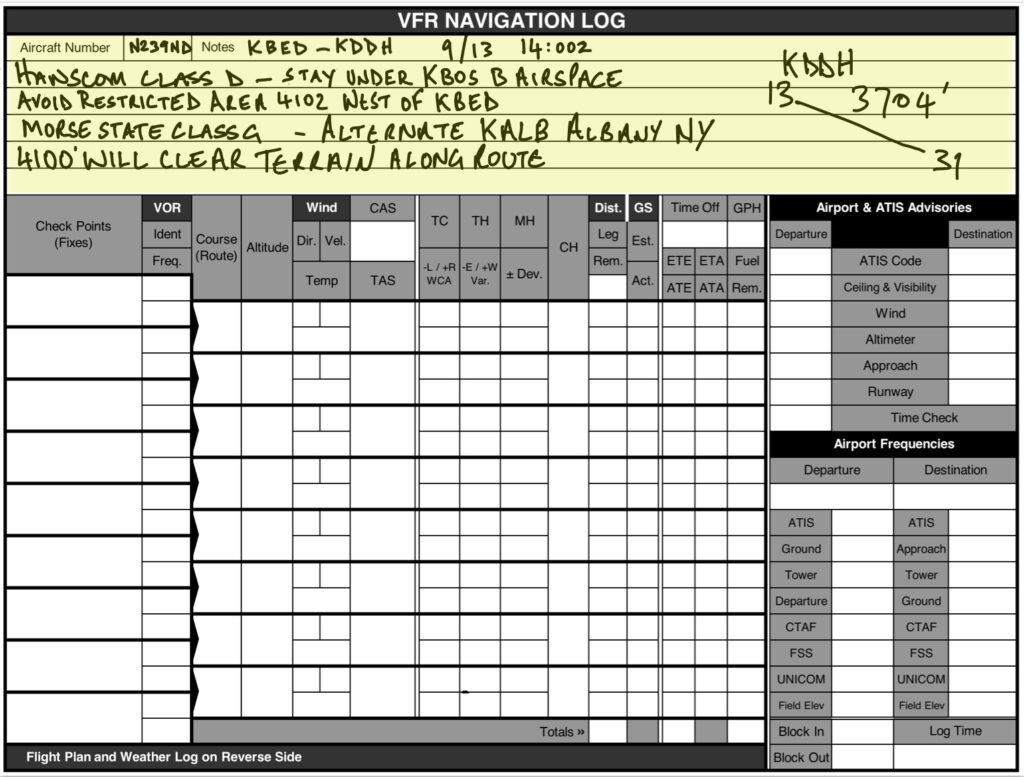
Filling out the Navigation Log
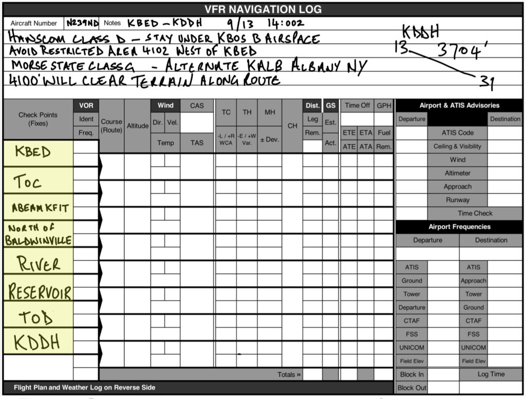
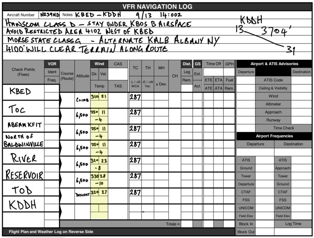
Flight Information
Begin by filling in the Nav Log with the details and information you have about the flight. This information should include:
- Date:
- Aircraft Type and Tail Number:
- Route of Flight : (Departure, Enroute, Arrival)
- Notes: Space for any pertinent information (such as runway diagrams etc)
Plot the course
Using a sectional chart, mark the course. If you are using a paper sectional chart draw the course on with a pencil using a plotter.
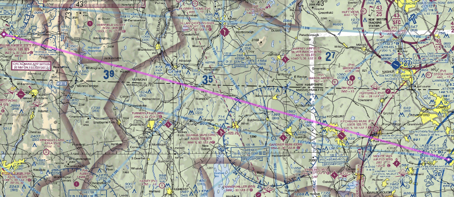
Enter Check Points / Leg Information
Using a sectional chart (or skyvector.com, mark ) the prominent landmarks found on the chart you will be using as check points along the route of flight. These landmarks should be between 15-25 NM apart. Any closer than 15 NM and you will be extremely busy looking for landmarks every few minutes, making it hard to note times, speeds, fuel burn etc. Any further apart than 25 NM – you may drift off course and not find the landmark you are looking for and get into a potential situation of getting lost.
Once you have found your checkpoints, mark them clearly on the chart along the route of flight and then list them in order in the Check Points column of your Nav Log.
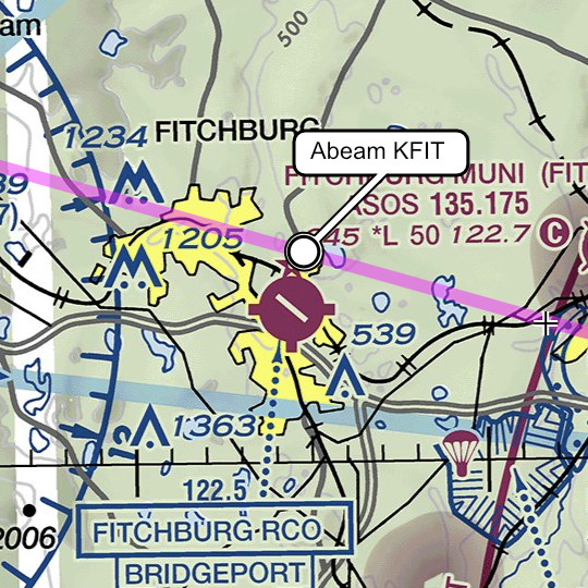
Abeam Fitchburg Airport
Overflying or close to airports is good for a number of reasons including.
- Emergency landing area.
- Altimeter & Weather updates (ATIS / AWOS).
- Easily seen from the air.
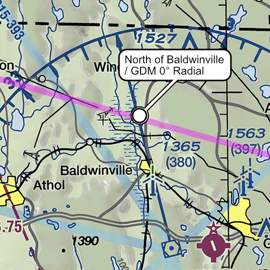
North of Baldwinville / GDM VOR 0° radial
Using KGDM (Gardiner) and the small town of Baldwinville you can identify you position with the added verification of using the GDM VOR 0° radial.
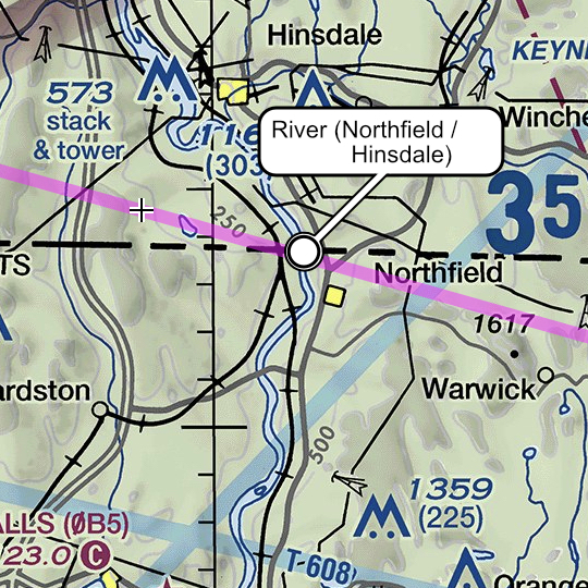
River
Crossing the river you will be able to identify the river and the towns of Northfield and Hinsdale.
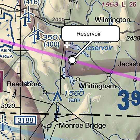
Reservoir
This reservoir is a prominent feature along the course of the flight. As you fly over the reservoir you will be able to see the body of water both the left if you and to the right. The wind turbines will also be visible to the northwest of the reservoir to assist in spotting the landmark.
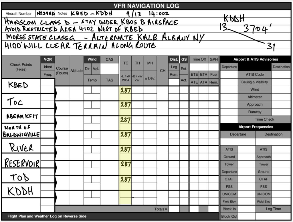
Enter True Course Information
True Course refers to your direction over the ground, referenced to true north (charts are printed to true north)
Using a plotter – find the true course in degrees for the route of your flight. If you have a straight course – this number will be the same for the entire flight. If you have to change course to route around obstacles or airspace this number will change.
Course = Direction over the ground
Heading = Direction aircraft is pointing (Wind can make heading to be different from course)
True (course or heading) = Referenced to true north pole (charts are printed to True) True north remains fixed.
Magnetic (course or heading) = Referenced to magnetic north pole (your magnetic compass in the aircraft points to magnetic north. The location of magnetic north changes over time.
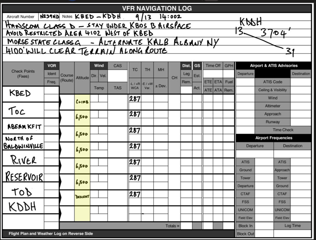
Enter Cruise Altitude(s) / Top of Climb & Top of Descent
Selecting a cruising altitude depends on several factors, including the type of aircraft, the route, weather conditions and air traffic control (ATC) regulations. Your route might dictate specific altitudes to avoid terrain or other obstacles that could be hazardous to the safety of the flight. Weather conditions can influence your cruising altitude.
- You might need to choose a higher altitude to avoid turbulence or to take advantage of favorable winds.
- You may not be able to fly as high as anticipated due to a cloud ceiling.
- Does your aircraft performance allow you to fly as high as you wish for example. Smaller general aviation aircraft might only operate at lower altitudes.
- Clear terrain.
- Adjust for weather. (You may not be able to fly as high as anticipated due to a cloud ceilings)
- Aircraft Performance limitations.
- Traffic avoidance: You may need to adjust your altitude to avoid other traffic, especially in congested airspace.
- Must be at appropriate VFR cruising altitude
- Eastbound: Odd thousands + 500ft.
- Westbound: Even thousands + 500ft.
91.159 – VFR Cruising Altitudes
- When > 3,000 feet above surface (AGL)
- Magnetic course between 0 and 179 deg. Odd 1000’s + 500 feet (e.g. 3,500 feet MSL)
- Mag. course between 180 and 359 deg. Even 1000’s + 500 feet (e.g. 4,500 feet MSL)
Calculating Winds and Winds Aloft
When flying at altitudes above 3000′ msl the you must refer to the winds aloft chart to calculate any required wind correction angles.
Winds aloft reports can be found at aviationweather.gov The data in the winds aloft report shows wind speed and direction at various altitudes above the Earth’s surface. These winds are typically measured at different increasing altitudes in the atmosphere, such as 3000′ 6000′ 12000′ etc.
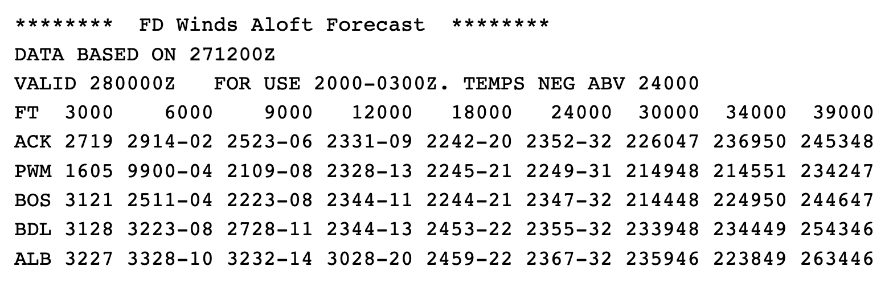
To calculate the winds that relate to your proposed flight
By noting the winds in the region and the closest reporting stations for your route of flight at the intended altitude you will be flying, you will be able to calculate the forecasted winds during the cross country flight for planning purposes. Interpolate, data if necessary.
Once you have calculated the winds for your route of flight – enter the data in the Nav Log, winds column.
Aircraft Performance
To ensure you have the most accurate aircraft performance data is essential for flight planning.
Aircraft performance data for your particular airplane can be found in the manufacturers Pilot’s Operating Handbook (POH).
Using the POH you will need to calculate:
- Climb performance for the climb portion of the flight immediately after takeoff. It is influenced by the aircraft’s weight, thrust, and air density.
- Cruise Performance During cruise, the airplane’s performance is optimized for fuel efficiency. Speed, altitude, and engine settings are adjusted to maximize range and minimize fuel burn.
- Landing Performance Factors like approach speed, flap settings, weight, and weather conditions affect landing performance.
- Landing performance calculations ensure safe stopping distances and appropriate handling on the runway.
- Fuel Efficiency and Range An airplane’s range and fuel efficiency are crucial for long-haul flights. Factors like altitude, engine power settings, and aerodynamic drag influence how far an airplane can fly on a given amount of fuel.
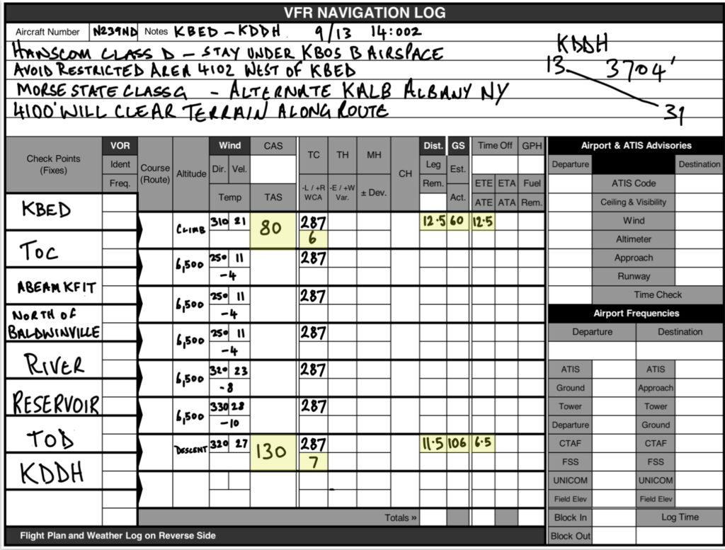
- Climb:
- BED: +4°C, 132 ft. field elevation = 642 ft. press. alt.
- TOC: -4°C, 6500 ft. cruise alt. = 7010 ft. press. alt.
- 2.5 gal., 12.5 min., 16.5 NM (still air)
- 75 KIAS = 75-80 KTAS
- Descent:
- TOD: -10°C, 6500 ft. cruise alt. = 6960 ft. press. alt.
- DDH: 2°C, 827 ft. field elevation = 1287 ft. press. alt.
- 2 gal., 6.5 min., 15 NM (still air)
- 124 KIAS = 124-134 KTAS
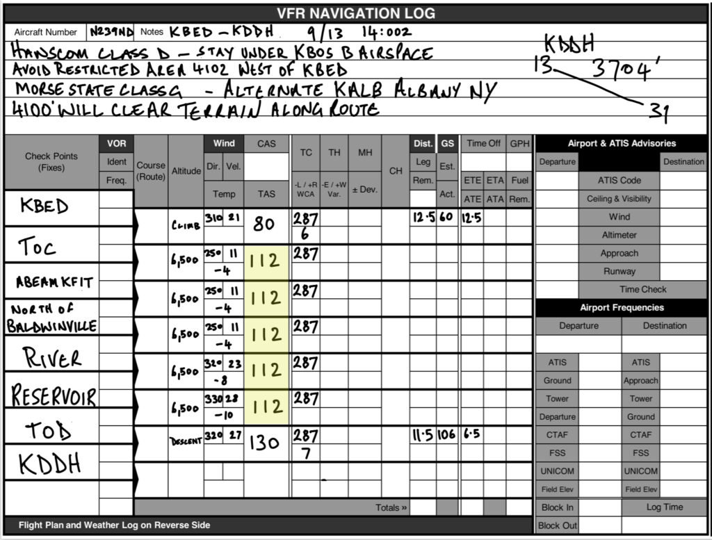
How fast will Piper PA28-151 go?
Piper Cherokee Warrior with 150 hp Lycoming O-320 engine. It has a higher gross weight (~2325 lbs.) than 1961 PA-28-150 (~2150 lbs.)
- Use performance charts or tables
- Pressure altitude = 7000 ft.
- PA28-151 @ 75% power: 112 KTAS
- Fuel Flow: 9.2 gallons per hour
Enter the airspeed into the chart (below)
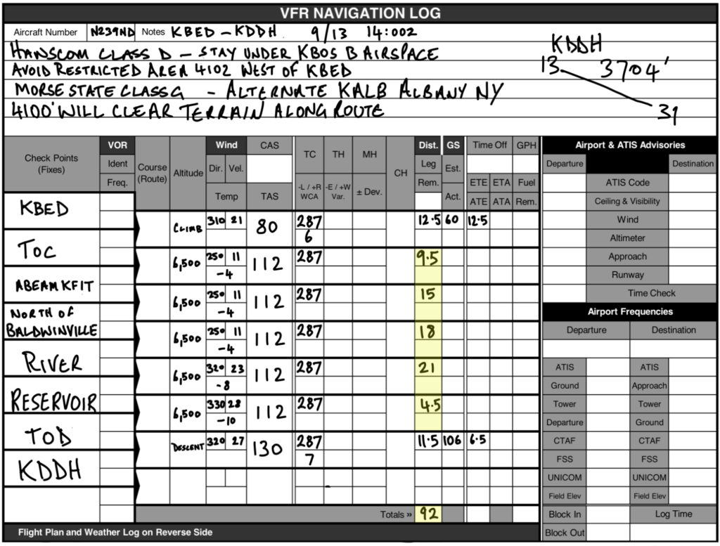
Leg Distances
Using a plotter measure the distances between the chosen Check Points on the sectional chart. Enter the leg distances on the Nav Log in the Dist column (below)
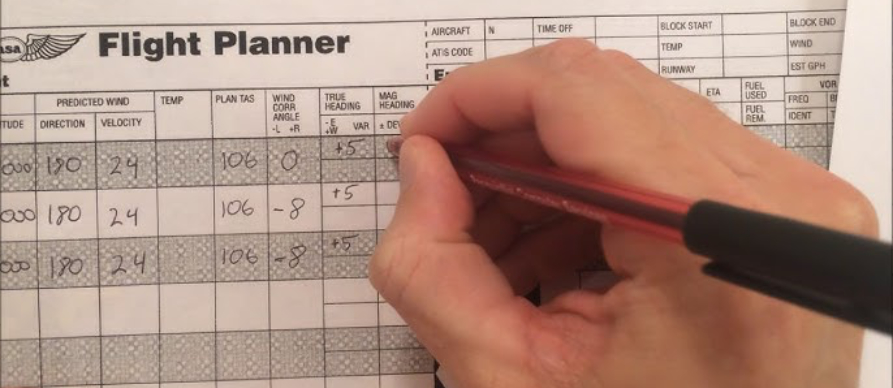
Wind Correction Angle
Whenever we fly – we are flying in weather of some description – usually wind, that is pushing on the aircraft in some manner – which can affect the course of the flight. The Wind Correction Angle (WCA) is the angle you need to adjust your aircraft’s heading to counteract the wind, ensuring you stay on your intended course. the wind correction angle is used to correct for the drift caused by the wind.
The Wind Correction Angle (WCA) is calculated using an E6B flight computer, using the wind side of the E6B.
Information Required
- True Course (TC): The intended course over the ground (in degrees).
- True Airspeed (TAS): The speed of the aircraft relative to the air (in knots).
- Wind Direction (WD): The direction from which the wind is blowing (in degrees).
- Wind Speed (WS): The speed of the wind (in knots).
Steps to Calculate WCA on an E6B
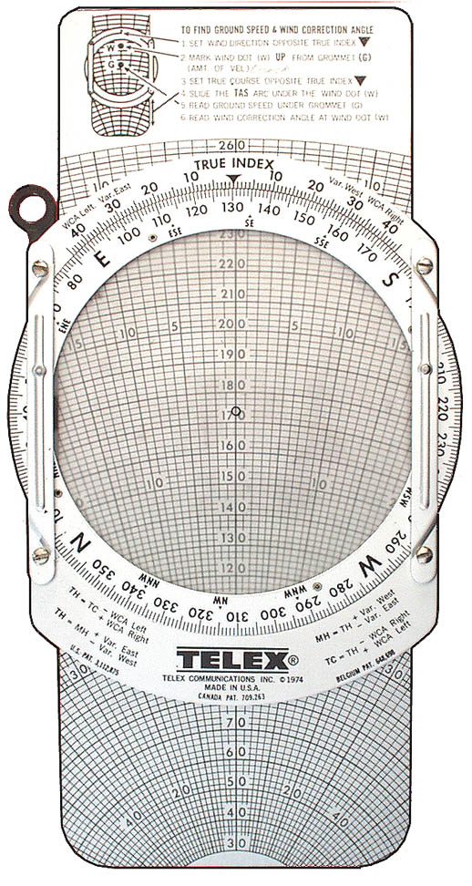
- Set Wind Direction (WD): Align the wind direction (in degrees) under the true index on the circular side of the E6B.
- Mark Wind Speed (WS): Using a pencil, mark the wind speed (in knots) from the center point outward on the grommet. The distance from the center represents the wind speed (knots).
- Set True Course (TC): Rotate the inner wheel so that your true course (in degrees) is under the true index.
- Align with True Airspeed (TAS): Move the sliding grid until the center of the grid aligns with your true airspeed (TAS). This is usually represented by an arrow or crosshairs on the E6B.
- Find the Wind Correction Angle (WCA): The lateral displacement of the wind mark from the center will give the wind correction angle. If the mark is left of center, the WCA is to the left (subtract it from TC); if it’s to the right, the WCA is to the right (add it to TC).
- WD is the wind direction in degrees.
- TC is the true course in degrees.
- WS is the wind speed in knots.
- TAS is the true airspeed in knots.
This formula will give you the angle (WCA) that needs to be applied to correct for wind drift.
- Note:
- If you see the wind direction written down = True
- If hear the wind direction spoken = Magnetic
Fill in True Heading and Ground Speed
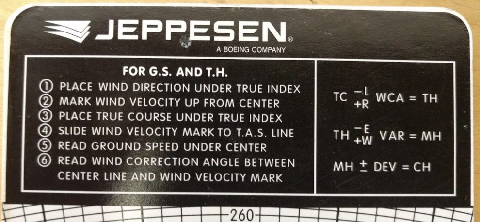
Using the E6B Wind Side
In most cases – E6B’s have a formula for calculating ground speed and true heading printed on the wind side of the computer. Follow these directions for a successful calculation.
- Wind Direction: 250°
- Wind Speed: 11 knots
- True Course: 287°
- True Airspeed: 147 knots
Magnetic Variation
Magnetic Deviation
- Depends on specific aircraft
- Compass correction card shows values
Research airport info in Chart Supplement
3. Wind and Weather Information
- Forecast Winds (At each leg):
- Speed/Direction
- Temperature
- Wind Correction Angle: (For adjusting course)
- Weather Conditions (Clouds, Precipitation, Turbulence, etc.)
4. Fuel Planning
- Start Fuel
- Fuel Reserve
- Fuel at Each Leg
- Fuel Used (Total)
5. Radio Frequencies
- Departure Frequency:
- Enroute Frequency:
- Arrival Frequency:
6. Aircraft Performance
- Climb Performance (Fuel and Time)
- Cruise Performance:
- Descent Performance:
- Gross Weight at Takeoff:
7. Alternate Airports
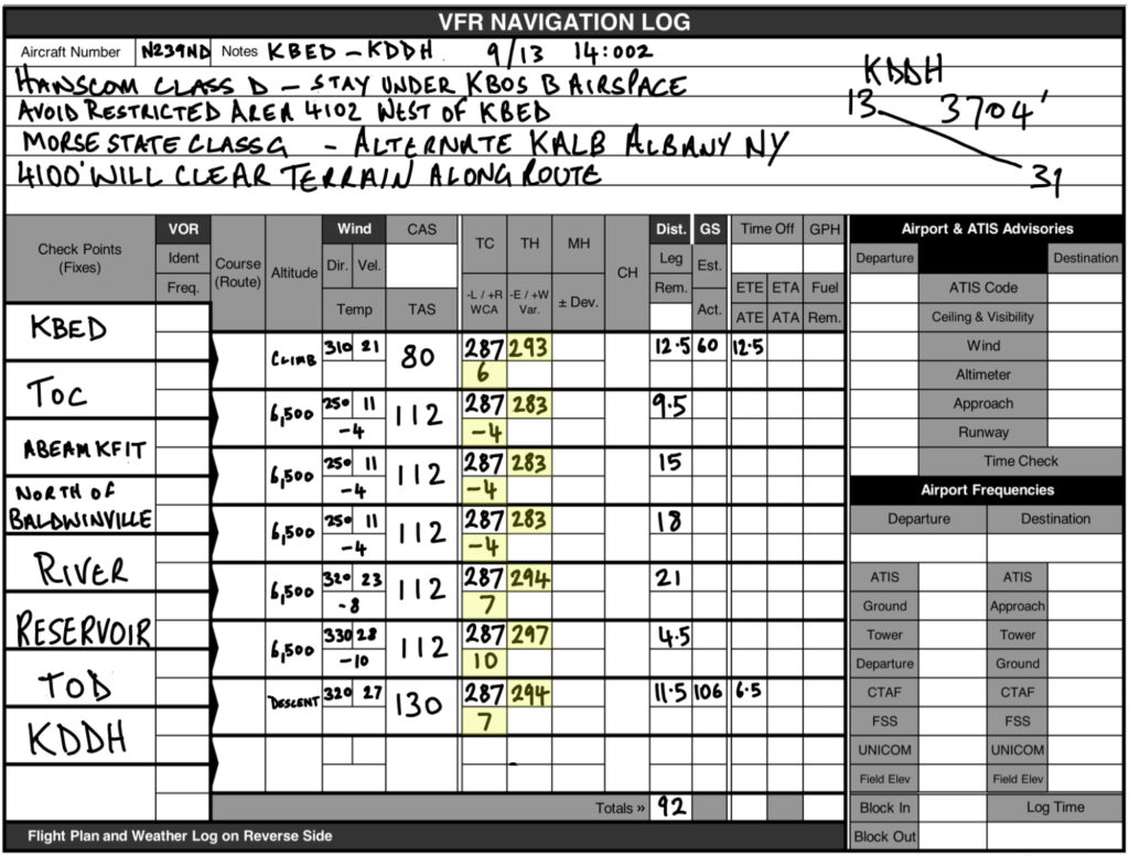
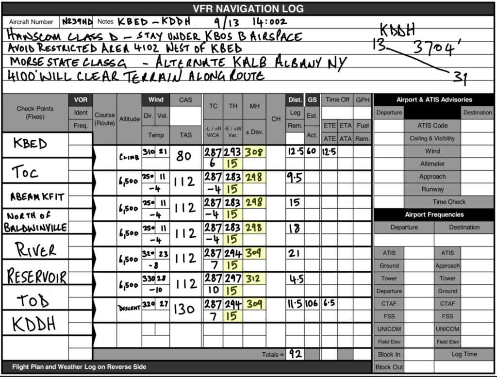
VFR Navigation Log
Editable PDF Navigation Log – click to download.