Flight instruments are crucial to conducting safe flight operations and it is important that the pilot have a basic understanding of their operation Various types of air navigation aids are in use today, each serving a special purpose
The “Six Pack”
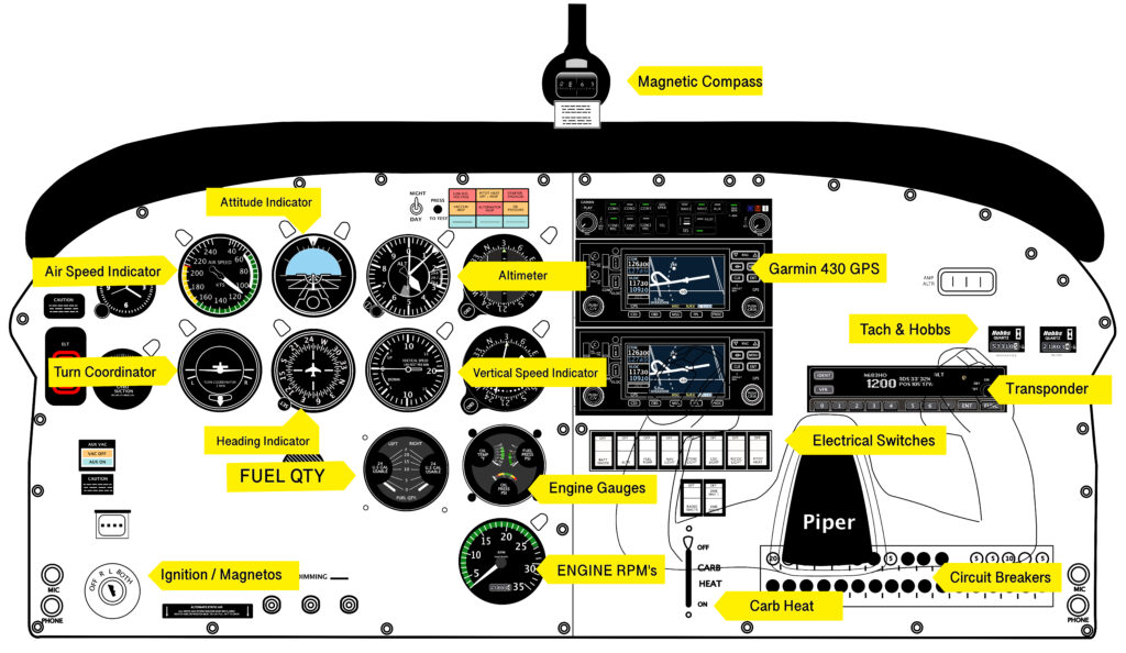
The core of the instruments in a standard training aircraft center around what is often referred to as “the six-pack” These instruments consist of:


Airspeed Indicator (ASI)
The airspeed indicator provides the pilot with a means of determining the speed of the aircraft. The airspeed indicator (ASI) is a required and crucial instrument for all aircraft during all phases of flight.
The airspeed indicator is vital for:
- Performance: Ensuring optimal aircraft performance and efficiency.
- Safety: Maintaining appropriate speeds for different flight phases (takeoff, cruising, landing) to avoid stalling or over-speed conditions.
- Navigation: Calculating accurate travel times and fuel consumption.
Components and Functioning
- Pitot Tube: Mounted on the exterior of the aircraft, this tube faces forward and captures dynamic air pressure (ram-air) caused by the aircraft’s motion.
- Static Port: Another opening that measures static air pressure, which is the ambient air pressure outside the aircraft.
- Differential Pressure Gauge: Inside the cockpit, the ASI uses a diaphragm or capsule connected to both the pitot tube and static port. The dynamic pressure (from the pitot tube) and static pressure (from the static port) act on opposite sides of the diaphragm.
- Needle and Dial: The diaphragm’s movement, caused by the difference between dynamic and static pressures, is mechanically linked to a needle on the ASI’s dial, displaying the airspeed.
Types of Airspeed
Speed is expressed in knots (KTS / KIAS)
- Indicated Airspeed (IAS): This is the direct reading from the ASI, showing the speed relative to the surrounding air.
- Calibrated Airspeed (CAS): IAS corrected for instrument errors and installation errors.
- True Airspeed (TAS): CAS corrected for altitude and non-standard temperature. It represents the actual speed of the aircraft relative to the air mass through which it is flying.
- Ground Speed (GS): TAS adjusted for wind effects, indicating the aircraft’s speed relative to the ground.
Markings on the Airspeed Indicator
- Vs: Stall speed with flaps retracted.
- VsO: Stall speed with flaps extended.
- Vfe: Maximum flap extension speed. (white arc)
- Vno: Maximum structural cruising speed.
- Vne: Never exceed speed. (red line or area)
- The green range is the normal range of operating speeds for the aircraft without flaps extended.
- The yellow range is the range in which the aircraft may be operated in smooth air, and then only with caution to avoid abrupt control movement.
- A redline mark indicates VNE, or velocity (never exceed). This is the maximum demonstrated safe airspeed that the aircraft must not exceed under any circumstances.
Understanding and correctly interpreting the airspeed indicator is crucial for pilots to ensure safe and efficient flight operations.
• Types of airspeed “ICE-T” or Indicated > Calibrated > Equivalent > True.

Attitude Indicator (AI)
The attitude indicator (AI), also known as an artificial horizon is an essential flight instrument that provides pilots with information about the aircraft’s orientation relative to the Earth’s horizon. It shows whether the airplane is pitched up or down, and if it is banked left or right. The “Miniature airplane” represents the actual wings and nose of the aircraft.
Functions of the Attitude Indicator
- Indicates pitch (fore and aft tilt) and bank or roll
- The Attitude indicator is split into two halves of the display. The top half is blue (or light) to represent sky and the bottom half is brown (or dark) to represent earth.
- Primary instrument for flight in instrument meteorological conditions and significant application under visual flight rules (VFR),
- Most light aircraft are not required to have them installed for VFR operation.
- If the symbolic aircraft dot is above the horizon line the aircraft is nose up. If the symbolic aircraft dot is below the horizon line (brown background) the aircraft is nose down.
- Fly the little airplane, not the horizon
Components and Functioning
- Gyroscope: The core of the attitude indicator is a gyroscope. The gyroscope is spun either electrically or via a vacuum system.
- Display: The display typically consists of a symbolic aircraft in the center, with a horizon bar that moves to indicate the aircraft’s pitch and bank.
- Pitch Scale: This scale shows degrees of pitch (nose up or down) in relation to the horizon line.
- Bank Scale (Gimbal): This shows the degrees of bank (left or right tilt) with marks for specific angles, often at 10, 20, 30, 45, and 60 degrees.
Functioning
- Pitch Indication: The horizon bar moves up and down to show the aircraft’s pitch relative to the actual horizon. When the nose of the aircraft rises, the horizon bar will descend on the indicator, showing a nose-up attitude. Conversely, when the nose drops, the horizon bar rises.
- Bank Indication: The miniature aircraft remains fixed in the center while the background moves. If the aircraft is banked to the left or right, the horizon line tilts to indicate the angle of the bank.
Importance in Aviation
- Spatial Orientation: The attitude indicator helps pilots maintain spatial orientation, especially in conditions where the natural horizon is not visible, such as in clouds, fog, or at night.
- Instrument Flight Rules (IFR): Under IFR conditions, the attitude indicator is crucial for maintaining the correct aircraft attitude and ensuring safe flight when external visual references are not available.
- Recovery from Unusual Attitudes: In the event of an unusual attitude, the AI provides the necessary information to correct the aircraft’s orientation.
Types of Attitude Indicators
- Traditional Mechanical Gyro-Based AI: Uses a spinning gyroscope to maintain a fixed plane of rotation. The aircraft symbol moves around this fixed plane to indicate attitude.
- Modern Electronic AI: Uses solid-state gyroscopes and accelerometers. These are often integrated into glass cockpit displays and provide more precise and reliable attitude information.
Limitations and Considerations
- Precession: Traditional mechanical gyros can suffer from precession, where the gyro axis shifts due to external forces, leading to slight errors over time.
- Power Source Dependency: Mechanical AIs depend on either a vacuum system or electrical power. A failure in the power source can render the instrument inoperative.
- Reliability of Electronic AIs: While modern electronic AIs are more reliable, they still depend on the aircraft’s electrical system and can be susceptible to power or system failures.
Interpretation of the Attitude Indicator
- Level Flight: The horizon bar aligns with the miniature aircraft’s wings.
- Nose-Up Attitude: The horizon bar is below the miniature aircraft.
- Nose-Down Attitude: The horizon bar is above the miniature aircraft.
- Bank Left: The horizon line tilts down to the right.
- Bank Right: The horizon line tilts down to the left.
The attitude indicator is an indispensable instrument in the cockpit, providing pilots with critical information needed to control the aircraft’s orientation and ensure safe flight.

Altimeter (Alt)
The altimeter is a flight instrument that measures and displays an aircraft’s altitude above a reference level, typically mean sea level (MSL). It provides pilots information of their vertical position and is essential for navigation, especially under instrument flight rules (IFR).
Components and Functioning

- Static Port: The altimeter receives static air pressure from the static port, which is an opening on the aircraft’s fuselage designed to measure ambient air pressure.
- Aneroid Wafers: Inside the altimeter are aneroid wafers that expand and contract with changes in air pressure. These capsules are sealed and contain a fixed amount of air.
- Mechanical Linkage: The movement of the aneroid capsules is transferred via mechanical linkages to the needles on the altimeter’s dial.
- Dial and Needles: The dial displays altitude in feet or meters. Typically, there are three needles: one for hundreds of feet, one for thousands of feet, and one for tens of thousands of feet.
Functioning
- Pressure Measurement: As an aircraft ascends, the external air pressure decreases, causing the aneroid wafers to expand. Conversely, as the aircraft descends, the air pressure increases, causing the capsules to contract.
- Altitude Indication: The mechanical linkage translates the expansion and contraction of the aneroid wafers into a corresponding movement of the needles on the altimeter’s dial, indicating the aircraft’s altitude.
Types of Altimeters
- Barometric Altimeter: The standard type that uses air pressure to determine altitude. Pilots must adjust the altimeter setting (via the Kollsman window) to account for changes in sea-level pressure to maintain accurate readings.
- Radio Altimeter: Measures the actual distance above the ground by bouncing radio waves off the terrain and timing their return. This is used for low-altitude measurements, typically below 2,500 feet above ground level (AGL).
Use in Aviation
- Flight Level: Altimeters help maintain assigned flight levels, ensuring proper vertical separation between aircraft.
- Navigation: Essential for terrain clearance and navigation, especially in mountainous areas.
- Approach and Landing: Crucial for descending to the correct altitude during instrument approaches.
- Altitude Awareness: Helps prevent controlled flight into terrain (CFIT) by maintaining altitude awareness.
Interpretation of the Altimeter
- Needle Readings: The longest needle typically indicates hundreds of feet, the middle-length needle indicates thousands of feet, and the shortest needle indicates tens of thousands of feet.
- Kollsman Window: Pilots set the altimeter to the current atmospheric pressure at sea level (QNH) or the pressure level at the departure airport (QFE) to ensure accurate altitude readings.
Limitations and Considerations
- Pressure Changes: Changes in atmospheric pressure due to weather can affect altimeter accuracy. Pilots must frequently update the altimeter setting.
- Temperature Effects: Extremely cold temperatures can cause altimeter errors, typically indicating a higher altitude than actual.
- Instrument Errors: Calibration and mechanical wear can introduce small errors.
Setting the Altimeter
- Standard Pressure Setting (29.92 inHg ): Used above the transition altitude to maintain standard pressure altitude for flight levels.
An altimeter is a device that measures altitude above sea level.
- Most altimeters are barometric, meaning they measure altitude by calculating the air pressure.
- In aircraft, an aneroid barometer measures the atmospheric pressure from
a static port outside the aircraft. - Air pressure decreases with an increase of altitude—approximately 100
hectopascals per 800 meters or one inch of mercury per 1000 feet near sea
level. - Displays aircraft altitude above mean sea level (MSL)
- Current altimeter setting must be set at each airfield and checked.
- The regional or local air pressure at mean sea level (MSL) is called the
“altimeter setting”, and the pressure that will calibrate the altimeter to show
the height above ground at a given airfield. - An altimeter cannot, however, be adjusted for variations in air temperature.
Turn Coordinator (TC)
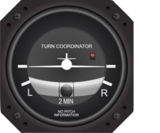
The turn coordinator displays the rate of turn as well as roll information and is used to coordinate of a turn (e.g., slipping or skidding) and the bank angle required for a specific rate of turn (e.g., 2 minutes for 360 degrees). The turn and slip indicator is an older version of the turn coordinator, providing only the rate of turn information.
The display of the Turn Coordinator consists of two parts
- The top part of the instrument is a depiction of a miniature airplane as seen from behind. The turn coordinator displays the rate of turn
- The bottom part of the instrument is the slip / skid Indicator (Inclinometer) The inclinometer is a black ball situated below the rate of turn indicator. This ball is suspended in a liquid that allows it to roll right, left, or remain in the middle of the tube, depending on the aircraft’s slip/skid (balance) condition.
The turn coordinator may be used as a performance instrument when the attitude indicator has failed. This is called “partial panel” operations. It can be unnecessarily difficult or even impossible if the pilot does not understand that the instrument is showing roll rates as well as turn rates.
This looks similar to that of an attitude indicator. “NO PITCH INFORMATION” is usually written on the instrument to avoid confusion regarding the aircraft’s pitch, which can be obtained from the artificial horizon instrument.
The turn coordinator’s gimbal is pitched up 30° from the transverse axis. This causes the instrument to respond to roll as well as yaw. This allows the instrument to display a change more quickly as it will react to the change in roll before the aircraft has even begun to yaw.
It is important to note – although this instrument reacts to changes in the aircraft’s roll, it does not display the roll attitude.

Heading Indicator (HI)
A heading indicator, also known as a directional gyro (DG), is a flight instrument that provides the pilot with the aircraft’s heading information relative to magnetic north. It supplements the magnetic compass, providing more stable and accurate readings, especially during maneuvers.
Components and Functioning
- Gyroscope: At the heart of the heading indicator is a gyroscope, which maintains its orientation due to the principle of rigidity in space. The gyro is typically spun either by an electric motor or by a vacuum system.
- Compass Card: A rotating card inside the instrument marked with headings (0° to 360°) that aligns with the aircraft’s heading.
- Adjustment Knob: Allows the pilot to periodically align the heading indicator with the magnetic compass due to precession errors.
Functioning
- Gyroscopic Stability: The gyroscope inside the heading indicator resists changes to its plane of rotation, maintaining a fixed position relative to the aircraft.
- Heading Indication: The aircraft’s movements cause the compass card to rotate around the fixed gyro. As the aircraft turns, the compass card displays the new heading relative to magnetic north.
- Periodic Adjustment: Because the heading indicator is subject to gyro precession, which causes the gyro to drift over time, the pilot must periodically realign the heading indicator with the magnetic compass.
Use in Aviation
- Navigation: Provides a stable and accurate reference for the aircraft’s heading, which is essential for navigating along a specific course.
- Maneuvers: More reliable than the magnetic compass during turns, climbs, and descents because it is not affected by magnetic dip or acceleration errors.
- Instrument Flight Rules (IFR): Crucial for maintaining accurate headings when visual references are not available, such as in clouds or at night.
Interpretation of the Heading Indicator
- Reading the Heading: The current heading of the aircraft is read at the top of the instrument where the index mark (lubber line) is located.
- Correcting Drift: The pilot uses the adjustment knob to realign the heading indicator with the magnetic compass at regular intervals to correct for gyro precession.
Limitations and Considerations
- Precession: Over time, the gyro in the heading indicator will drift due to mechanical imperfections and friction, requiring periodic realignment with the magnetic compass.
- Power Dependency: Mechanical heading indicators rely on either the aircraft’s vacuum system or electrical power. A failure in the power source can render the instrument inoperative.
- Alignment with Magnetic Compass: Must be regularly cross-checked with the magnetic compass to ensure accuracy.
Steps for Using the Heading Indicator
- Initialization: Before takeoff, align the heading indicator with the aircraft’s magnetic compass.
- Monitoring: During flight, monitor the heading indicator and cross-check with the magnetic compass every 10-15 minutes or when significant course changes are made.
- Adjustment: Use the adjustment knob to correct any drift observed during the cross-checks with the magnetic compass.
The heading indicator is an indispensable instrument for ensuring accurate and stable heading information, enhancing both navigation precision and overall flight safety.

Vertical Speed Indicator (VSI)
The Vertical Speed Indicator (VSI), also known as or rate-of-climb indicator, is a flight instrument that measures the rate at which an aircraft ascends or descends. It provides real-time feedback on the aircraft’s vertical speed, typically in feet per minute (fpm)
Components and Functioning
- Static Port: Like the altimeter, the VSI uses the aircraft’s static port to measure ambient air pressure.
- Diaphragm or Capsule: Inside the VSI, there is a diaphragm or capsule connected to the static port, which expands and contracts with changes in static air pressure.
- Calibrated Leak: The instrument includes a calibrated leak (a small, precise restriction) that allows air to flow slowly into or out of the instrument case, creating a slight delay.
- Indicator Needle and Scale: The movement of the diaphragm is mechanically linked to an indicator needle that moves over a graduated scale showing the rate of climb or descent.
Functioning
- Pressure Changes: During a climb, the outside static pressure decreases, causing the pressure inside the diaphragm to be higher than the pressure in the instrument case, which causes the diaphragm to expand. During a descent, the opposite occurs.
- Rate Indication: The rate at which the diaphragm expands or contracts (due to the calibrated leak causing a delayed equalization of pressure) translates into vertical speed. The indicator needle moves up for a climb and down for a descent, showing the rate of vertical movement.
Use in Aviation
- Maintaining Desired Climb/Descent Rates: Pilots use the VSI to maintain a steady rate of climb or descent, especially during critical phases of flight like takeoff, approach, and landing.
- Situational Awareness: It helps in maintaining situational awareness regarding the aircraft’s vertical motion, aiding in smooth and controlled altitude changes.
- Instrument Flight Rules (IFR): Under IFR conditions, the VSI is essential for executing precise altitude changes without visual references to the ground or horizon.
Interpretation of the Vertical Speed Indicator
- Climb: If the needle points above the zero mark, the aircraft is climbing. The position of the needle indicates the rate of climb.
- Descent: If the needle points below the zero mark, the aircraft is descending. The position of the needle indicates the rate of descent.
- Level Flight: When the needle is at the zero mark, the aircraft is in level flight with no vertical speed.
Limitations and Considerations
- Lag: The VSI typically has a slight lag due to the calibrated leak, meaning it doesn’t instantly show changes in vertical speed. The lag can be more pronounced in turbulent conditions.
- Errors: Rapid pressure changes or turbulence can cause temporary errors in the VSI reading. It’s crucial for pilots to cross-check with other instruments.
- Sensitivity to Small Changes: Some modern VSIs are more sensitive and can detect smaller changes in vertical speed, providing more precise information.
Types of Vertical Speed Indicators
- Conventional VSI: Provides a delayed indication of the rate of climb or descent due to the calibrated leak.
- Instantaneous VSI (IVSI): Uses accelerometers to provide more immediate vertical speed readings, reducing the lag found in conventional VSIs.
Steps for Using the Vertical Speed Indicator
- Initial Climb/Descent: During takeoff or when beginning a descent, monitor the VSI to establish and maintain the desired rate of climb or descent.
- Cruise Adjustments: Use the VSI to make small altitude adjustments during cruise flight to maintain level flight.
- Approach and Landing: During the approach phase, the VSI helps ensure a stable descent rate to the runway.
The VSI is an essential instrument for maintaining control over an aircraft’s vertical motion, enhancing both safety and efficiency in various flight phases.